Zylo Solar
China’s leading solar power systems combine rooftop panels, metal frames, inverters, batteries, and complex wiring. Safe grounding connects these parts to a controlled fault path. It also reduces shock risks, equipment damage, and fire hazards during insulation failures or lightning events.
This guide explains How to ground a solar power system safely, using practical principles for Chinese installations. The process includes bonding the panel frames, mounting rails, inverter enclosure, battery cabinet, and protective conductors. A ground rod alone may not provide adequate protection. The complete grounding network must be continuous, secure, and compatible with the building’s existing earthing system.
Details matter. Inspectors and experienced installers check conductor size, corrosion, loose lugs, sharp metal edges, and water entry points. They also verify continuity with suitable test equipment before energizing the system. Local requirements may involve Chinese GB standards, utility rules, and site-specific fire regulations. A qualified electrician should confirm the final design, especially for high-voltage batteries or commercial arrays.
Small mistakes can remain hidden.
For example, a painted rail may look bonded while blocking electrical contact. An undersized wire may pass a visual inspection but fail during a fault. Good work therefore requires drawings, labeled connections, torque checks, and recorded test results. It is also wise to review the design after expansion, roof repairs, or inverter replacement. Grounding is not a one-time assumption. It deserves careful testing throughout the system’s service life.
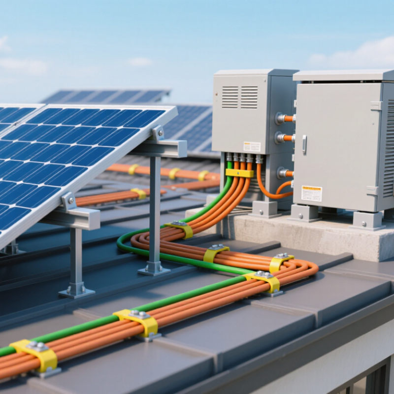
China’s solar expansion makes grounding a design priority, not a final inspection task. The IEA PVPS Trends 2024 report states that China added about 216.9 GW of photovoltaic capacity in 2023. Its cumulative capacity exceeded 600 GW. More installations mean more exposed metal, cables, and switching equipment.
Chinese projects commonly reference GB/T 16895.32-2021, aligned with IEC 60364-7-712, and GB 50797-2012 for photovoltaic power-station design. These requirements support protective earthing, equipotential bonding, and suitable overvoltage protection. Mounting frames, inverter enclosures, cable trays, and other accessible conductive parts should connect to the protective earthing network. The grounding method must match the low-voltage system, soil conditions, lightning exposure, and fault-protection design. A single resistance value cannot safely fit every site. That assumption causes trouble.
Tips: Use listed, corrosion-resistant conductors and protect connections from water and loose fasteners. Test continuity before energizing, then measure earth resistance with calibrated instruments. Keep records for each array and inverter. Installers should verify conductor sizing, bonding points, and separation from lightning conductors against the approved drawings. Field conditions often differ from plans. Recheck after heavy rain, construction changes, or unusual inverter faults. IEA PVPS data shows rapid deployment, but speed should not replace documented testing and competent supervision.
China Top Solar Power Systems: How to Ground Them Safely?
Safe grounding begins by identifying every conductive part that could become energized. Bond solar module frames to the mounting rails with listed bonding hardware. Connect the rails to the equipment grounding conductor. Do not rely on metal contact through paint, dirt, or loose bolts.
Check the inverter chassis, combiner box, disconnect enclosure, and metal conduit. Each needs a reliable bonding path. The grounding electrode conductor should connect to the building’s approved grounding electrode system. DC negative grounding is not always required. Many modern systems use isolated, transformerless designs. Follow the system instructions and local electrical requirements.
Protection components deserve equal attention. Install correctly rated overcurrent devices on circuits that need them. Use DC and AC disconnects where required. Surge protective devices can reduce damage from lightning-induced voltage, but they cannot replace proper bonding. Keep conductors short, protected, and mechanically secure.
Field inspections often find one missing bonding jumper or a corroded connection. Small details matter. I still treat every grounding plan as provisional until measurements and inspections confirm it. A continuity test can reveal hidden weaknesses, while a qualified electrician should verify the final installation. Never connect a conductor to a random water pipe or structural part. That shortcut looks convenient, but it may create a dangerous fault path.
Choosing suitable grounding methods and materials is central to safe solar installation. The IEA PVPS Trends 2024 report recorded about 456 GW of new photovoltaic capacity worldwide in 2023. That rapid expansion increases the importance of reliable protective bonding, especially on large rooftop and utility systems.
IEC 62548:2023 emphasizes protective earthing, equipotential bonding, and clear fault-current paths. Use copper conductors where corrosion risk is controlled, or listed aluminum conductors where the design permits them. Copper commonly offers about 97% to 100% IACS conductivity, while aluminum is lighter but needs greater cross-sectional area. Tinned copper can help in humid or coastal locations. Stainless-steel hardware is often useful near salt exposure, but compatibility still requires checking.
Keep the path short and mechanically protected. Bond module frames, mounting rails, equipment enclosures, and the grounding electrode system according to the applicable electrical code. NFPA 70, Article 690, provides widely used requirements for photovoltaic circuits and grounding. Follow the manufacturer’s specified torque values; loose lugs can create heat, arcing, and hidden resistance. Very tight connections can also damage thin metal.
Avoid direct contact between incompatible metals without approved fittings. Galvanic corrosion is easy to miss beneath a washer. Field inspections often find damaged insulation, buried connections, or missing labels. A neat installation is not automatically a durable one. Check continuity, torque, corrosion, and electrode resistance during commissioning and scheduled maintenance. Local soil conditions may change the best grounding method, so one universal material choice is rarely enough.
Safe solar installation begins with bonding every exposed metal part into one reliable fault-current path. Bond the module frames, mounting rails, equipment enclosures, combiner boxes, and disconnects with approved bonding hardware. Do not rely on paint, loose fasteners, or ordinary washers. Remove coatings only where the bonding method permits it.
Grounding and bonding are related, but they are not identical. Bonding connects conductive parts together. Grounding connects the system to an approved grounding electrode system. A qualified electrician should follow the local electrical code, equipment instructions, and site conditions. Never use gas pipes or improvised metalwork as grounding paths. Keep conductors protected from sharp edges, standing water, and direct sunlight where required.
Before energizing, check conductor continuity with suitable test equipment. Confirm each connection is tight, corrosion-resistant, and protected from moisture. Torque matters. Over-tightening can damage a lug, while under-tightening can create heat.
Field inspections often find one forgotten enclosure or a damaged cable jacket. That small mistake can defeat an otherwise careful installation. Use lockout procedures and verify the array is electrically safe before touching it.
No checklist is perfect. Reinspect after severe weather, roof repairs, or visible corrosion. A clean cable route may look impressive, but the real test is a dependable bond during a fault.
As solar installations expand, grounding deserves routine attention, not a one-time handover check. The IEA PVPS Trends 2024 report records more than 1.6 terawatts of global photovoltaic capacity by the end of 2023. Every additional array adds connections, joints, and possible fault paths. A safe grounding network should bond module frames, mounting rails, inverter enclosures, and other exposed conductive parts.
Testing should begin with a visual inspection. Look for loose lugs, damaged copper, oxidation, buried conductors, and water near junction boxes. Then verify protective conductor continuity with a calibrated low-resistance meter. Measure earth resistance using a suitable fall-of-potential or clamp method. The acceptable value depends on soil, system design, and local requirements. One universal number is misleading. A low reading can still hide a loose bond.
IEC 62446-1 supports documented verification of photovoltaic systems, while NREL’s photovoltaic operation and maintenance guidance stresses repeatable inspections and recorded electrical measurements. Keep test dates, instruments, weather conditions, readings, and corrective actions together. Recheck after lightning, flooding, construction, or inverter replacement. Torque marks on terminals help reveal movement during later visits. Small details matter. Still, field teams sometimes test only the main earth electrode and overlook rail-to-rail continuity. That habit needs reconsideration. Corrosion under a washer may remain invisible until a fault occurs. Annual inspection is a practical baseline, but harsh coastal, agricultural, or high-lightning sites may require shorter intervals.
| Inspection Area | What to Check | Recommended Test or Method | Typical Acceptance Benchmark | Suggested Frequency | Corrective Action |
|---|---|---|---|---|---|
| Protective Bonding | Bonding between module frames, mounting rails, inverter enclosures, combiner boxes, cable trays, and the main earthing terminal. | Visual inspection followed by low-resistance continuity testing with a calibrated micro-ohmmeter or multifunction installation tester. | Continuous metallic connection with no loose, painted, oxidized, or contaminated contact surfaces. Use the project design value and applicable electrical code as the final criterion. | During commissioning, after modifications, and during scheduled maintenance. | Clean contact surfaces, replace damaged bonding hardware, tighten to the specified torque, and restore corrosion protection. |
| Equipment Grounding Conductor | Conductor size, insulation condition, routing, mechanical protection, identification, and connection to exposed conductive parts. | Compare installation with approved drawings and local code; perform continuity and polarity checks before energization. | Conductor size and routing must comply with the governing design and code. The protective conductor must not be interrupted by switches, fuses, or disconnect devices unless specifically permitted. | Commissioning and annual visual inspection; inspect after construction or cable work. | Replace undersized or damaged conductors, correct routing, and secure all terminations. |
| Grounding Electrode System | Ground rods, concrete-encased electrodes, buried ring conductors, grounding grids, inspection pits, and connections to the main earthing terminal. | Visual inspection, conductor continuity testing, and earth resistance testing using the three-point fall-of-potential method where practicable. | Meet the value specified by the engineering design and local regulations. A low resistance value alone does not prove that bonding, touch voltage, or step voltage requirements are satisfied. | At commissioning; after lightning, flooding, excavation, or major civil work; and at the interval required by local rules. | Repair broken conductors, improve electrode connections, add electrodes only when supported by an engineered assessment, and retest. |
| Earth Resistance Measurement | Resistance of the complete grounding electrode system and the influence of parallel paths. | Use the fall-of-potential method with auxiliary current and potential electrodes. Keep test probes sufficiently separated and confirm stable readings. | Repeat measurements at multiple probe positions. Readings should be consistent and interpreted with soil conditions, electrode geometry, and parallel metallic paths considered. | Commissioning and periodic maintenance, especially when seasonal soil moisture changes significantly. | Investigate unstable or unexpectedly high values before adding electrodes. Check disconnected bonds, damaged conductors, poor soil contact, and test-lead placement. |
| Clamp-On Ground Testing | Ground current and loop resistance on multi-grounded systems where parallel return paths exist. | Use a clamp-on ground resistance tester only on suitable closed-loop or multi-grounded arrangements. | Use as a screening or trend method unless the instrument method is proven suitable for the site. It is not a substitute for fall-of-potential testing on an isolated electrode. | Routine maintenance and trend monitoring. | Confirm abnormal readings with an appropriate direct test and inspect the associated bonding path. |
| Lightning Protection Bonding | Separation or bonding between the photovoltaic array, support structure, DC and AC wiring, surge protection devices, and lightning protection system. | Review the lightning-risk assessment and drawings; inspect separation distances, equipotential bonding, down conductors, and surge protection device connections. | Follow the lightning protection design and applicable lightning protection standard. Do not create unintended parallel paths or reduce required separation distances. | Commissioning, after structural changes, and after a known lightning event. | Correct separation or bonding deficiencies and replace surge protection devices that show an end-of-life indication or damage. |
| Surge Protection Devices | AC and DC surge protection devices, protective device status indicators, conductor length, grounding connection, and backup protection. | Visual inspection; verify wiring configuration, conductor routing, and manufacturer-specified status indication. Test or replace devices according to the approved maintenance procedure. | Status indication must show serviceable condition; connections must be short, secure, and correctly coordinated with the system voltage and earthing arrangement. | At commissioning, during routine maintenance, and after suspected surge or lightning damage. | Replace failed or operated modules with compatible components and investigate the cause of repeated operation. |
| Connection Integrity | Bolted joints, crimped lugs, irreversible connectors, exothermic welds, and accessible test links. | Visual inspection, torque verification against the approved installation specification, and thermal imaging under suitable load conditions. | No looseness, overheating, discoloration, arcing marks, cracking, or corrosion. Torque values must come from the approved equipment or project documentation. | Visual inspection at least annually and after severe weather; thermal inspection when abnormal heating is suspected. | De-energize safely, repair or replace the connection, remove corrosion, and document the retest. |
| Insulation and Leakage | DC circuit insulation to earth, cable damage, moisture ingress, and unintended current paths. | Perform insulation-resistance testing only after isolating sensitive equipment and following the approved photovoltaic test procedure. | Meet the minimum insulation-resistance value specified by the governing standard, equipment documentation, and project design. Never apply a test voltage that could damage connected electronics. | Commissioning, after repairs, and when insulation monitoring or inverter alarms indicate a fault. | Locate and isolate damaged cables, wet connectors, contaminated junction boxes, or defective equipment before re-energization. |
| Touch and Step Voltage | Potential differences around equipment, inverter stations, metallic fences, transformer areas, and accessible structures. | Carry out a site-specific assessment and, where required, measure touch and step voltages using approved instruments and test conditions. | Values must remain within the limits set by the applicable electrical and safety standards for the site voltage, fault duration, soil conditions, and public accessibility. | During design verification, commissioning, and after major changes to the grounding network. | Improve equipotential bonding, surface insulation, electrode layout, or access control based on an engineered assessment. |
| Corrosion and Soil Conditions | Rust, galvanic corrosion, chemical exposure, soil drying, flooding, erosion, and damage to buried conductors. | Visual inspection of accessible components; document soil conditions and compare resistance trends over time. | No material loss that could reduce mechanical or electrical integrity. Dissimilar metals must be compatible or suitably separated. | At least annually and after flooding, earthworks, chemical spills, or coastal exposure events. | Replace degraded parts, use compatible materials, seal suitable interfaces, and repair disturbed soil or protective coverings. |
| Testing Equipment Control | Calibration status, test-lead condition, measurement category, battery condition, and operator competence. | Inspect instruments before use and verify calibration certificates and measurement-category ratings. | Equipment must be appropriate for the system voltage and test task, in good condition, and within its calibration interval. | Before each test session; calibration according to the instrument quality program. | Remove defective or overdue instruments from service and repeat affected measurements with valid equipment. |
| Records and Trend Analysis | Test date, weather and soil conditions, test method, probe spacing, measured values, instrument identification, defects, and corrective actions. | Maintain a grounding test register with drawings, photographs, certificates, and comparison with previous results. | Records must be complete, traceable, and sufficient to reproduce the test. Investigate significant changes rather than relying only on a single pass/fail result. | Update after every inspection, test, repair, or system modification. | Close outstanding defects with responsible person, target date, repair evidence, and verification results. |
| Safe Work Procedure | Isolation, lockout/tagout, backfeed prevention, photovoltaic DC generation in sunlight, and personal protective equipment. | Use an approved switching and test procedure; verify absence of hazardous energy where applicable and treat PV circuits as energized in daylight unless properly isolated. | Only qualified personnel may perform electrical testing. Test boundaries, arc-flash controls, and local occupational-safety requirements must be followed. | Before every inspection, test, or repair activity. | Stop work if the circuit condition or documentation is unclear; establish safe isolation before touching conductors or grounding connections. |
Grounding helps control fault current and reduces touch-voltage risks. It connects exposed metal to a reliable protective path. More panels mean more frames, rails, cables, and enclosures to inspect.
Bond module frames, mounting rails, inverter enclosures, combiner boxes, cable trays, and disconnect cabinets. Every accessible conductive part needs attention. One forgotten enclosure can weaken the whole fault path.
No. Bonding connects conductive parts together. Grounding connects the system to an approved grounding electrode system. Both functions matter, but they solve different problems.
No single value works safely everywhere. Soil, moisture, system design, lightning exposure, and local requirements affect the result. A low reading does not prove every bond is secure.
Use approved, corrosion-resistant conductors and compatible bonding hardware. Protect connections from standing water, sharp edges, and excessive sunlight. Do not rely on paint, loose bolts, ordinary washers, gas pipes, or improvised metalwork.
Inspect every bond and cable route visually. Test protective-conductor continuity with calibrated equipment. Confirm correct conductor sizing, secure torque, intact cable jackets, and safe lockout procedures.
Measure continuity and earth resistance using suitable test methods. Record the date, instrument, weather, readings, and corrective actions. Test only the main electrode? That misses rail-to-rail problems.
An annual inspection is a practical baseline for many sites. Inspect sooner after lightning, flooding, heavy rain, roof repairs, construction changes, or inverter replacement. Coastal and high-lightning locations may need shorter intervals.
This guide explains how to ground a solar power system safely in China by first understanding the system’s electrical grounding requirements, site conditions, and relevant safety expectations. It identifies key grounding points, including photovoltaic panels, mounting structures, inverters, batteries, distribution equipment, and protective devices. The article also discusses how to select suitable grounding conductors, electrodes, connectors, and corrosion-resistant materials according to the installation environment.
It then presents practical steps for bonding all conductive parts into a reliable grounding network, reducing the risk of electric shock, equipment damage, and lightning-related faults. Special attention is given to secure connections, proper conductor routing, weather protection, and separation from unrelated electrical systems. Finally, the guide explains how to test continuity and resistance, inspect connections regularly, identify corrosion or loosening, and maintain the grounding network throughout the system’s service life. Following these procedures helps installers build a safer, more dependable solar power installation.
